Update: Version 1.2 is available now; read about it here:
At my church, we have two auditoriums, each with their own video switcher and cameras. All of the inputs and outputs of each switcher are on a common video router, so all of these sources can easily be shared across both rooms. However, even with all this, we have no camera tally system. Commercial tally systems can be expensive, and it’s just something we’ve never been able to afford.
It’s not normally an issue, but sometimes we want to pull up a shot of a camera in Auditorium 1 and show it in Auditorium 2. Because we have no tally system, the camera operator would not know their shot was being used. And, even if we did have a tally system, those systems generally only interface with one tally source/switcher, not multiple sources at the same time.
A few weeks ago, I was quarantined from work due to a co-worker testing positive for COVID-19. I set out to use this time to write a tally system for our church to use. Now that we’ve re-opened for church services, we will really need this, because we will have cameras capturing the service to stream online, but won’t necessarily have those cameras visible on the projector screens in the auditoriums during that time, where the operators would at least have a visual reference if their shot was in use.
And, because we have two video switchers, I needed to come up with a solution that would allow either video switcher to pull up a camera in either auditorium in Preview or Program, and make sure the operator still knew their shot was in use.
So here is Tally Arbiter. I called it this because the software aggregates tally data from multiple sources and “arbitrates” whether that device is in Preview, Program, or both across all sources and buses.
The server software is written in Node.js and can run on a Raspberry Pi. It supports the TSL 3.1 network protocol like what our Ross Carbonite switchers use, but I’ve also written support for Blackmagic ATEM switchers, OBS Studio, StudioCoast VMix, and Roland SmartTally. I plan to one day add support for incoming webhooks, and GPIO inputs for switchers that don’t have network-based protocols.

The software supports tally data coming from multiple sources, and each source can vary in protocol type. This could be useful, for example, if you had shared cameras for your production on-screen using an ATEM and also through your live stream using OBS or VMix, and you need the cameras to reflect the tally data of either system.
You can configure multiple devices in the software. These would be what generally receives tally data, whether it be cameras, CG stations, monitors, etc. Each device can support addressing from multiple sources. This is the “arbitration” portion of the software.
Once a device is determined to be in preview and/or program, device action(s) can be run. This can be sending out a TSL 3.1 protocol message (to a monitor/scope/multiviewer), an outgoing webhook (to tell another device to start playing a video (“roll clip”), for example), triggering a relay if you have CCUs that need contact closures to turn on the tally lights, or even local console output for logging and testing.
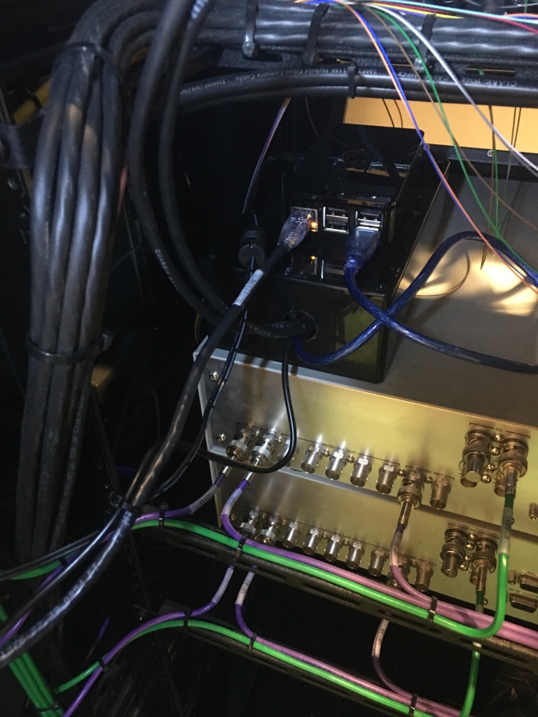
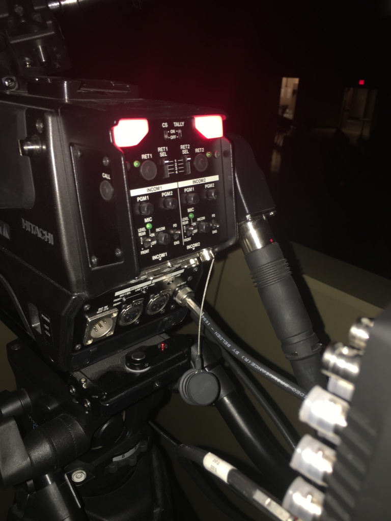
Some of our cameras have built-in tally lights, like the two Hitachi Z-HD5000 cameras we have. For those, I implemented a separate relay controller client that listens to the data on the Tally Arbiter server. It uses simple USB relays with the Node.js library I created a couple years ago that controls our auditorium window shade.
I bought a project box, put the relay in, ran some CAT5e cable I had laying around and connected it to the relay and the CCU’s with custom DB25 connectors. I had to modify the project box some because I wanted the relay to sit flat in the box, so I used a dremel to remove the bottom of the middle screwposts, which weren’t really needed anyway. Never be afraid to modify something to make it work!


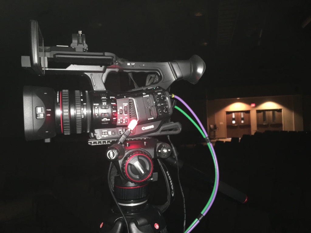
But what about the cameras we use that don’t have tally lights? For these, I decided to use Raspberry Pi Zero W‘s that would run software listening over websockets to the Tally Arbiter server. These particular Pi models are inexpensive and simple to use. I knew that I could get the least expensive cost for physical tally lights out of these Pi’s if I went the GPIO route with some LED lights and custom circuitry, but I wanted to design something that people who may not be comfortable with these concepts could easily implement. And honestly, the thought of soldering something just sounded like something I’d have to possibly maintain down the road. So, I used the blink(1) USB lights by ThingM.
I first started experimenting with these USB lights about a year ago when I created a silent notification system for our band to use in case we had a tech issue during a service. The company that makes these has published very easy to use APIs, which makes it a great tool to use with custom software.


The listener client script is written in Python since that programming language runs so easily on the Raspberry Pi OS no matter what model Pi you have. And, since we are using the socket.io websocket libary, bi-directional real-time communication between the server and clients even though the programming languages vary is not an issue.

All together, each wireless tally light should cost between $55 and $60 depending on what Pi case you use, SD cards, etc. Tally Arbiter has no built-in limitation of the number of wireless clients that can be connected, so this makes it a very versatile and flexible system no matter what the size is of your production.
Lastly, I also created an option to view live Tally data in a browser, like on a tablet or phone. You can select the device from the list and the background of the page will be red, green, or black depending on that device’s tally state.
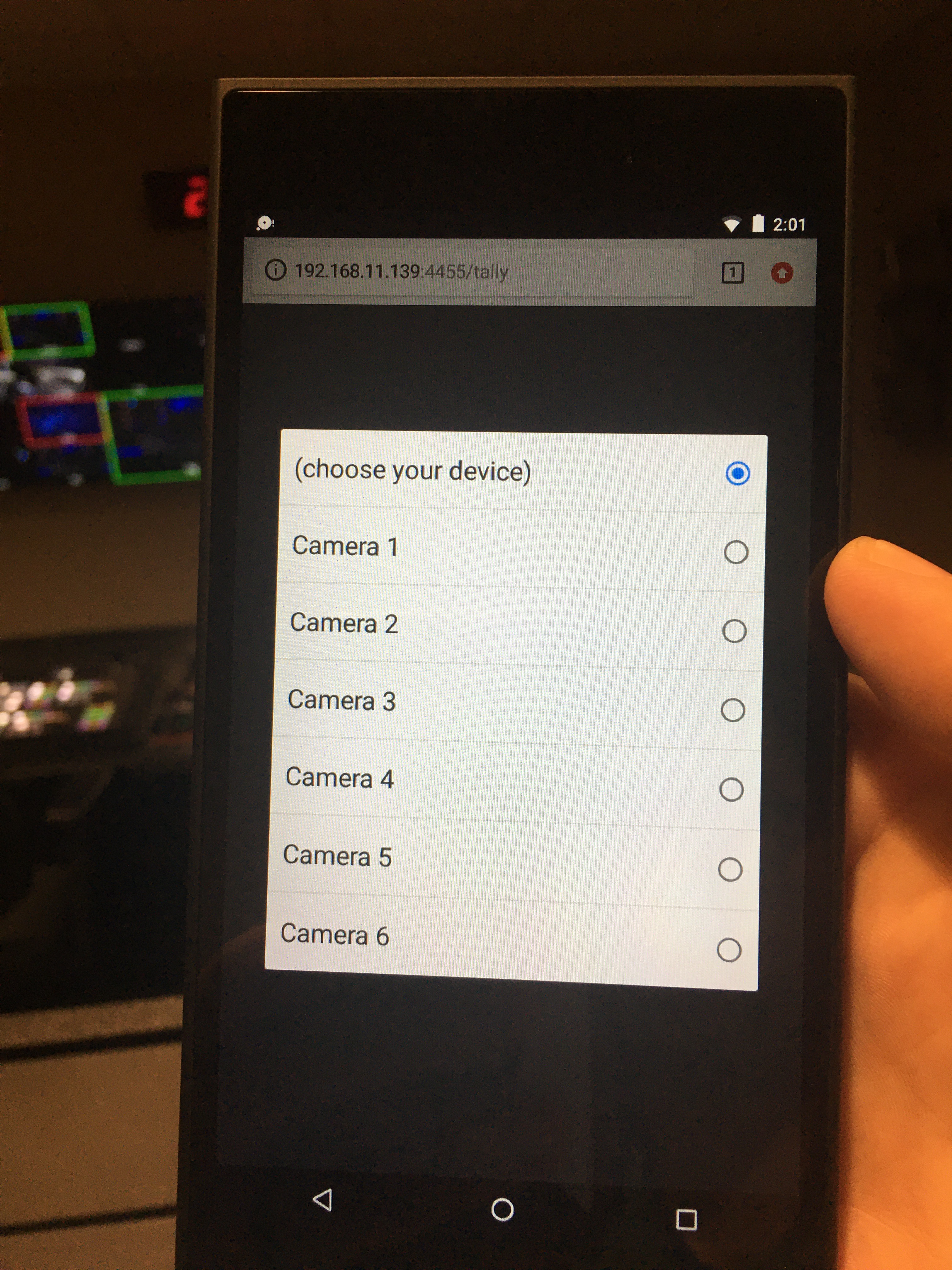
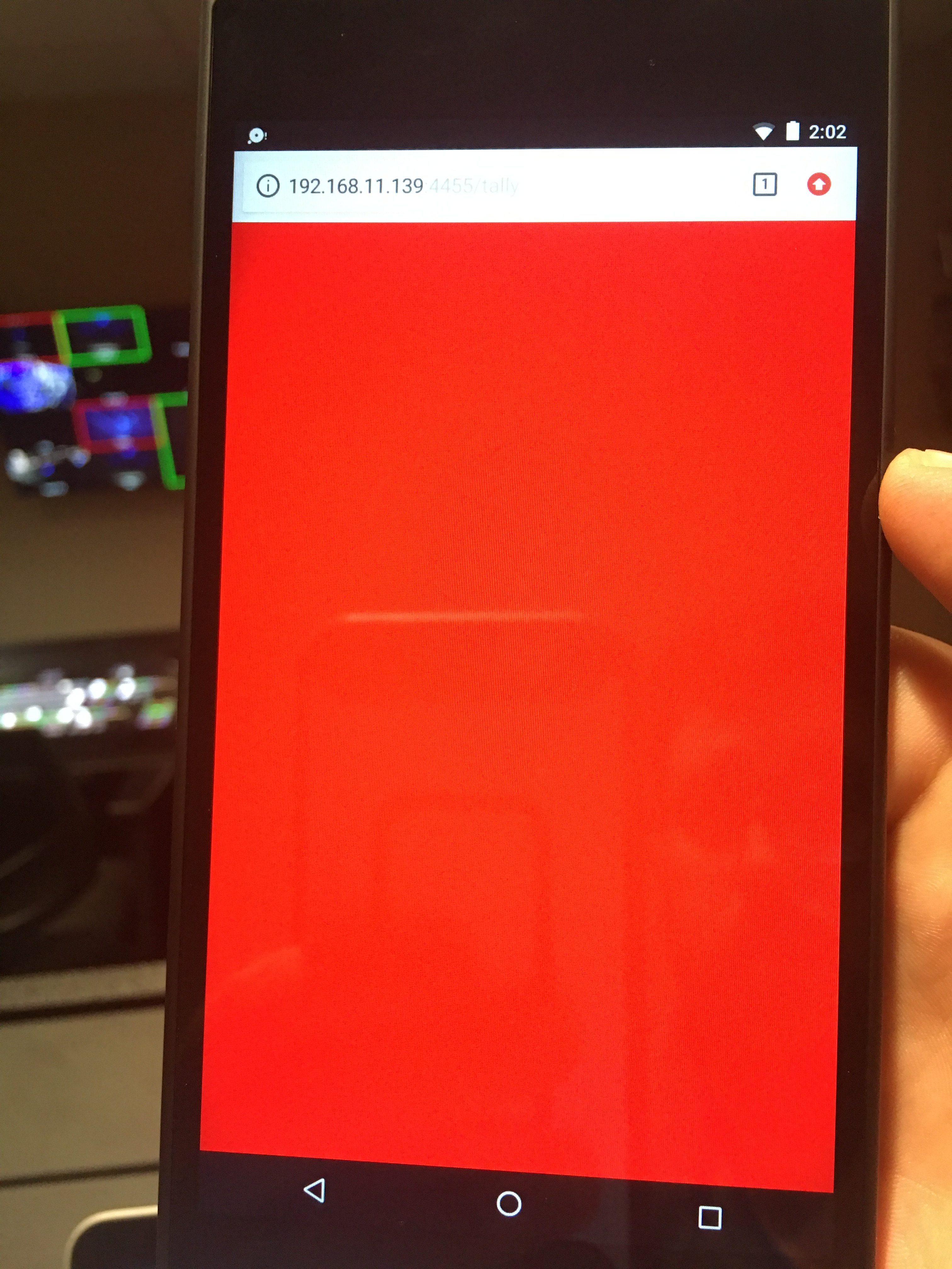
The web tally is controllable through the Settings page just like any other listening client, so you can reassign the tally remotely and even send a flash to that client to get their attention.
Here’s a walkthrough video of the whole system in action:
As usual with my projects, I’ve made this open-source and available for your use on Github: http://github.com/josephdadams/TallyArbiter. It is fully documented with a REST API if you want to automate use of it outside of the GUI that I have created. There are also step-by-step instructions on how to set up a Raspberry Pi Zero, with OS imaging and all of of the libraries and script installing needed to get it going.
My hope and passion is to see resources like this to be used to further the Gospel. I believe and have seen that God can use technology for His good, and when we can use it to further ministry, that is how we can see the Gospel spread.
If these projects are helpful to you and your church, let me know! I love hearing how you use technology to serve the church.

Upon receiving cell signal when my plane landed, I saw that you’d posted a new article. I read the entire thing before setting foot on the jet way. It’s so good! You’re incredibly generous to offer this up for other churches to use. Happier volunteers, more coordinated direction, more comprehensive worship experience, more attention on God. Thanks for doing this!
LikeLiked by 2 people
This is so awesome! I have been searching endlessly for a solution like this. I am no programmer but read through your detailed instructions and decided to give it a shot. Just ordered everything. Thanks for working on this, this will really help out our church
LikeLiked by 1 person
This is a wonderful answer to prayer. Our 5 camera Television OB van is under construction, we have 7″ Lilliput 663 camera monitors with built in green / red tallys but have never come up with a method of getting the tally signal out of out ATEM switcher. the BMD “decoder” is very costly and is not even complete as it needs the relay board. We will build with capability for 4 cameras wired to monitor tallys plus one for a mobile camera that will have to be wireless. Many thanks, I will keep in touch.
John Fickling
Endtime TeleVision
Havelock North,
New Zealand
LikeLiked by 1 person
This is great. I now need to research what options I have for getting preview tally out of some Tricaster TC1s. The GPIO only outputs program tally.
LikeLiked by 1 person
Let me know what you find out! I would love to expand what TA can support. I have a “GPI software interface” that could run on a Pi and integrate with TA on the to do list.
LikeLike
You should take a look at the Automation and Integration Guide from Newtek for the Tricasters. There are several options, but the easiest would probably be to use their TCP socket and listen for tally events. They will come back as XML like this:
I’d also like to say your blog is awesome. Lots of good ideas here. I am ordering some Pi’s this week and already have the tally server running with our ATEM switcher. Big thanks for sharing your hard work!
LikeLiked by 1 person
Great idea! Tricaster support would be a good addition. I will put it on the list! Thanks!
LikeLike
Love this! Will definitely be testing this out this week and hope to implement it soon! Love all that you do on this blog, huge inspiration!
LikeLiked by 1 person
Cant handshake with BMD Atem Switcher.
Its connected to it: shows green label
Mapped to listener with input: 1
Output to Console
After changing input nothing happen
LikeLike
Well, green is good! Do you have a source assigned to the device? Click “Device Sources” next to the device you created. It should have the input number that corresponds to the address or input on the ATEM.
LikeLike
I did.
Log output:
Device Source Added: CAM 1 – ATEM Switcher
Listener Client Connected. Type: web Device: CAM 1
and nothing happend on tally page
LikeLike
Send me a message here through the blog and I’ll respond from my email address, or you can email me directly: jadams at fellowshipgreenville.org. I want you to send me your config.json file so I can take a look and then we can figure out what might be going on. Thanks!
LikeLike
Cant handshake with BMD Atem Switcher.
Its connected to it: shows green label
Mapped to listener with input: 1
Output to Console
After changing input nothing happen
LikeLike
Are you the same person as Kostyantyn? You commented the same thing.
LikeLike
Sorry. Hit button twice)))
LikeLiked by 1 person
Does terminal have to stay open the entire time when running from directly within NODE?
I figured out a very basic apple script for a one double click option for the NODE route so I think this would work for us but my OCD doesn’t like seeing the terminal application running.
I get a missing write access error when I try to set it up as a Service. Are you able to add to your walkthrough on GitHub to maybe best resolve this?
How are you activating/running the code in your application at your church (Direct or Service)?
Thanks for doing this!
LikeLiked by 1 person
Hey Chad! If the post doesn’t make it clear, I’m running it on a Raspberry Pi. I designed it with that platform in mind, hence it runs as a terminal process. But, the beauty of Node.js, it can run on many operating systems! So, yes, the terminal window will need to stay open. If you’re getting a write access error, it’s possible you are not running the process with the necessary permissions. An easy fix would be to run it with administrative (root) privileges. But it’s possible you could also grant specific permissions also. When you say “as a Service”, I’m just asking for clarification, you’re trying to use pm2 with MacOS?
LikeLike
Yes that’s correct pm2 with MacOS at home to try it out. Yes you did say Raspberry Pi now that I think about it but I was thinking about putting it on my mac and there were Pi Zeros at the camera so that probably confused me too. Essentially once the “terminal” Pi is running, it can stay on and active in kind of a set it and forget it?
LikeLike
Yes in general once TA is running, you won’t need to look at the terminal process for anything. You can manage it all through the web browser Settings page. I haven’t run it on anything less than a Pi 3B+ for the server so I would say that’s probably the safest minimum until I get a report that someone is running it on less. https://www.raspberrypi.org is a great place to get started!
LikeLike
Also I’ll try pm2 on MacOS and see if I can raise the error you’re getting and post a solution.
LikeLike
Is there a recommended Raspberry Pi model minimum? Also, I’ve heard of Raspberry Pi in the past but never educated myself on it. Do you have a suggested site(s) that you’ve found helpful in my situation?
LikeLike
Hello, I tried this today and it looks like I’m having the same result as Kostyantyn and dkosta10. I’m on an ATEM 4M/E and using an iMac. I’m able to get a green light pretty quickly to confirm the software can “see” the switcher. Just when I set up a camera and select it, nothing else changes.
LikeLiked by 1 person
I confirmed they are the same person. Can you send me your config file also? Also I will have a TA 1.1 release this week for you to try that should help troubleshoot. It’s working fine with my ATEM here. Are you running TA on the same computer as your ATEM software?
LikeLike
yes, its same computer where TA and Atem Software
LikeLike
Sorry I read that earlier and thought putting both of them sounded funnier in my head than in type. I can try and get the config file to you hopefully tomorrow. Yes TA and ATEM on same computer. I’m working on getting Raspberry or something on an old NUC that was sitting around as a permanent solution.
The config file is just copied from the TA folder?
LikeLike
Yep, it’s called config.json and is in the TA folder. For kicks try closing out the ATEM software and then disable and re enable the ATEM connection in TA. Thanks!
LikeLike
This helped me. But LIVE status not red on 2nd device when set in Atem Software control. Its Yellow color on listening page (/tally page)
LikeLike
Yellow means you have the input in both preview and program simultaneously.
LikeLike
I successfully installed Raspian on a NUC from 2012 but I’m only able to get node v10.21.0 and npm v5.8.0 installed. Can you confirm this setup is inadequate for TallyArbiter?
Thank you.
LikeLike
It’s probably fine. I’m not pushing the boundaries of Node to accomplish this. NPM should report any errors when it grabs all the libraries.
LikeLike
I’m inexperienced with Raspberry and pretty much everything else. I’m able to query version numbers for NPM and Node so they should be installed? I copied your folder from Github to the raspberry desktop. Switched to the folder via command line and attempted to start a service. But that is where i get stuck. Are you able to help me with the next steps?
LikeLike
Are you getting an error message? Send me an email with screenshots if you think that would help.
LikeLike
I just tried it again and I was able to get it to load directly within Node. I wasn’t able to get to install as a service on Raspberry. I just sent a screenshot of what I’m getting.
LikeLike
We recently got an iKan vx9w monitor which has an Rj45 port labeled tally. Would you expect we would have to construct one of the relays you describe in order to send tally to the monitor?
LikeLike
Most likely, yes. I’ll see what I can find on documentation for that monitor.
LikeLike
You can actually see the tally pinout here on the back of the monitor: https://ikancorp.com/prod1/wp-content/uploads/2018/03/VX9wOV_053.jpg
What I am not sure about is whether it is contact-closure based or voltage based. You could test for this by just taking a spare RJ45 cable and cutting/splitting one end and connecting the wires to see if it turns on the tally or not. This is what a relay would do. If not, then you’ll need to use the GPO client with Tally Arbiter.
LikeLike
Great work! What I need to do is pass on the ATEM tally signal to Datavideo PTC-140 cameras (same Visca as PTC-150) by sending a hex packet by TCP to the IP of the camera (same network) port 5002. Packet is 00 0B 81 01 7E 01 0A 00 0r 0g FF where r/g = 2(on)/3(off). I don’t think I can use Tally Arbiter to do that; could you confirm I am not missing something: the logic is there to send the messages, but not the required message protocol? Thanks
LikeLike
Correct. Tally Arbiter cannot currently send TCP as an output action. A workaround would be to send OSC or HTTP to an app that could then send out TCP. Companion can do this. I will add TCP out in a later update.
LikeLike
Jonathan, the latest release on Github can now send generic TCP. Hope this helps.
LikeLike
This is fantastic. I think I may be able to control the built-in Tally on JVC PTZ cameras with a properly formed TCP string.
Chris Glanzer
LikeLike
Let me know how that goes! I’d love to be able to include a how-to for others. Maybe even add some presets for common gear.
LikeLike
I Can’t Make it work with my phone, how do I use it as a tally light?
LikeLike
It looks like you’ve commented multiple times here as well as on my YouTube channel. I’ll answer you once here and reference that answer on YouTube as well.
LikeLike
I Can’t Make it work with my phone, how do I use it as a tally light?
LikeLike
Are you getting an error message? Make sure that the Settings page is showing tally accurately. That can help rule out configuration issues.
LikeLike
Hi thanks for your reply (and sorry for multiple comments, I messed it a bit!!). I get an ERR_CONNECTION_FAILED on my phone. Am I supposed to run the server on my phone too? how do I do it?
LikeLike
This sounds like it could be a networking problem. Are your phone(s) on the same network or wifi as the server?
LikeLike
Yes same WiFi network. When I go to http://127.0.0.1:4455/tally from any mac browser it works but if I try to open it from my phone it does not.
Should I change any setting in the router firewall or port forwarding?
LikeLike
127.0.0.1 is your computer’s local/internal IP. To access the server from your phone, you need to reference the computer’s wifi network IP. Go to System Preferences, Networking, and you can see your wIfi IP there.
LikeLike
Ok Joseph thanks a lot for your support, I didn’t get it right but now it works perfectly on both phone and tablet!
Thanks again, you did a great job!
LikeLike
I downloaded the software but have no idea how to create a user name and password?
LikeLike
Dale, this documentation may help: https://josephdadams.github.io/TallyArbiter/docs/usage/control-interface
LikeLike